Where Condensate Management Goes Wrong in Cooled Enclosures
The cooling module is running correctly. The compressor cycles as expected. Internal temperature holds within specification. Then, three months into deployment, a circuit board corrodes, a connector develops intermittent faults, or a relay welds shut. The root cause is water — condensate generated by the cooling process itself — that was never properly managed.
Every vapor-compression cooling system produces condensate. When warm, humid air passes over the evaporator coil, the coil surface temperature drops below the dew point of the internal air, and moisture condenses on the fins. In a household air conditioner, this water drains through a pipe to the outside. In a sealed electronics enclosure, there is no outside. The water stays inside the cabinet, and condensate management becomes a design problem that the cooling module alone cannot solve.
This guide covers the failure modes caused by unmanaged condensate in DC-cooled sealed enclosures, the engineering approaches that prevent them, and the design decisions that determine whether condensate is a non-issue or a reliability risk over the life of the system.
Why Sealed Enclosures Generate More Condensate Than Expected
In a sealed enclosure, the total moisture content is theoretically fixed — no new humid air enters the system. Engineers often assume that the initial moisture inside the enclosure will condense during the first few cooling cycles, and then the problem disappears because the internal air becomes progressively drier.
This assumption fails for several reasons:
- Seals are rarely perfect. IP55 and even IP65 enclosures allow small amounts of air exchange over time, especially during thermal cycling when internal pressure fluctuates. Each pressure equalization event introduces ambient humidity into the enclosure.
- Gaskets and cable glands degrade. UV exposure, vibration, and temperature cycling reduce seal effectiveness over months and years. An enclosure that was airtight at commissioning may have measurable air exchange after 18 months of outdoor deployment.
- Maintenance access introduces moisture. Every time a technician opens the enclosure door for inspection, maintenance, or component replacement, the internal air is replaced with ambient air at ambient humidity. In tropical or coastal environments, a single door opening can introduce enough moisture for significant condensation during the next cooling cycle.
- Component outgassing and hygroscopic materials contribute moisture. Cable insulation, PCB substrates, thermal interface materials, and adhesives release small amounts of moisture over time, especially when heated.
The practical result is that condensate generation in sealed enclosures is not a one-time event. It is a recurring process that continues throughout the life of the equipment, and the condensate management strategy must account for continuous — not just initial — moisture removal.
Failure Modes: What Happens When Condensate Is Not Managed
Unmanaged condensate in electronics enclosures causes failures through several mechanisms, and the time between condensate accumulation and visible failure can range from weeks to years — making the root cause difficult to identify in post-failure analysis.
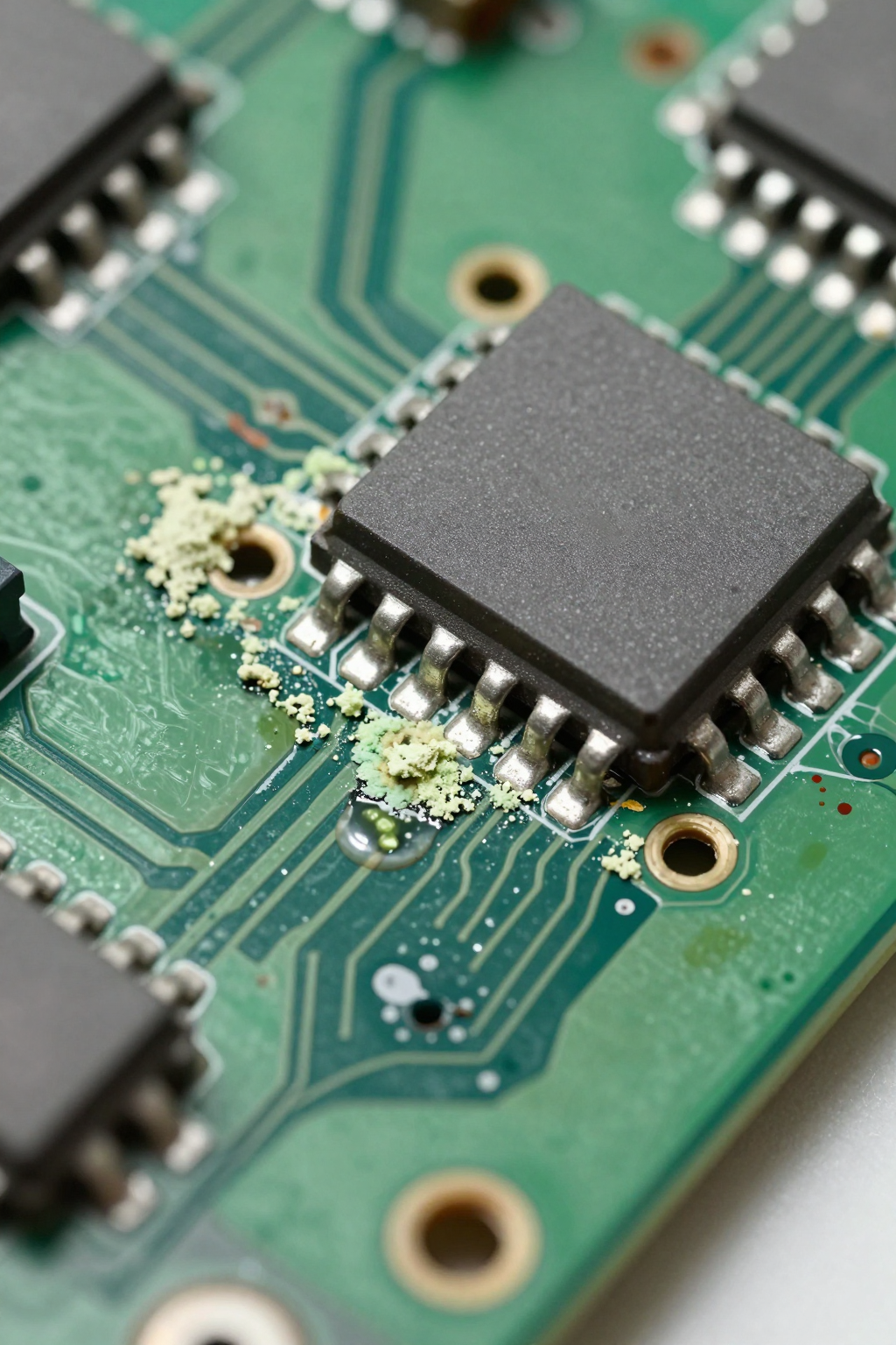
Electrochemical Corrosion
When water contacts a PCB surface with residual flux or ionic contamination, it creates an electrolyte that enables electrochemical migration between conductors. Copper dendrites grow along the surface from one trace to an adjacent trace, eventually bridging the gap and creating a short circuit. This process is slow — often taking months — and the failure is typically intermittent before it becomes permanent. The corrosion products are sometimes visible as green or white deposits near fine-pitch component leads.
Connector Degradation
Water droplets on connector pins accelerate oxidation of the contact surfaces. Gold-plated connectors resist this for longer than tin-plated ones, but even gold plating has micro-pores that allow moisture to reach the base metal. The result is increased contact resistance, which causes signal integrity problems in data circuits and voltage drops in power circuits. In high-vibration environments, oxidized contacts can produce intermittent opens that are nearly impossible to diagnose without removing and inspecting each connector.
Insulation Resistance Degradation
High-voltage circuits are particularly sensitive to moisture. The insulation resistance between conductors decreases when a moisture film forms on the surface. In power electronics operating at hundreds of volts, even a thin moisture film can reduce insulation resistance below safe thresholds, leading to leakage currents, partial discharge, and eventually dielectric breakdown. This failure mode is temperature-dependent — it often appears only when the cooling module brings the enclosure temperature below the dew point during nighttime or low-load conditions.
Optical Component Degradation
In enclosures containing optical transceivers, laser diodes, or sensors with optical windows, condensate on optical surfaces causes signal attenuation and scattering. Even microscopic water droplets on a fiber connector end-face can increase insertion loss by several decibels. In telecom enclosures, this manifests as gradual signal degradation that worsens during cooling cycles and partially recovers during warm periods.
Evaporator Pan Design: The First Line of Defense
The evaporator pan — a collection tray beneath the evaporator coil — is the most basic and most critical condensate management component. Its function is to catch all water that drips from the evaporator fins and direct it to a controlled location where it can be drained or re-evaporated.
The design requirements seem simple, but the details matter:
- The pan must extend beyond the evaporator coil footprint on all sides. Condensate does not always drip straight down — airflow across the coil carries droplets laterally, and vibration in mobile applications causes water to shift. A pan that matches the coil footprint exactly will miss edge drips.
- The pan must slope toward the drain point. A flat pan allows water to pool in unpredictable locations and increases the risk of overflow. A minimum slope of 2 to 3 degrees toward a single drain point ensures consistent drainage under all mounting orientations.
- The pan material must resist corrosion. Aluminum pans corrode in the presence of condensate (which is essentially distilled water with trace contaminants from the air and coil surface). Stainless steel or coated aluminum is typical for industrial applications. Plastic pans work well but must be rigid enough to maintain slope under thermal cycling.
- The pan must be accessible for inspection and cleaning. Over time, dust and biological growth (mold, biofilm) can accumulate in the pan, blocking the drain and creating a contamination source. If the pan is permanently sealed inside the cooling module with no access, long-term reliability is compromised.
Drain Routing: Getting Water Out of the Enclosure
In enclosures where external drainage is permitted (the enclosure has a drain port that maintains the IP rating), a gravity drain is the simplest and most reliable condensate removal method. A tube from the evaporator pan exits the enclosure through a sealed fitting and drips to the ground or into a collection container.
Drain routing considerations:
- The drain line must slope continuously downward from the pan to the exit point. Any sag or upward loop creates a trap where water accumulates and eventually blocks the line. In cold climates, trapped water freezes and blocks the drain entirely.
- The drain exit must include a trap or check valve to prevent ambient air from entering the enclosure through the drain line. A simple U-trap filled with water provides a seal, but the trap must be deep enough to prevent the water seal from evaporating in dry conditions.
- The drain line diameter should be at least 12 to 15 mm internal diameter for typical electronics enclosure applications. Smaller diameters are prone to blockage from dust, biological growth, or ice.
- The drain exit must be positioned where dripping water does not cause problems — not above electrical conduit, not where it pools on a roof surface, and not where it freezes into an ice dam that blocks the drain.
For enclosures where external drainage is not possible — rooftop telecom cabinets, sealed military enclosures, underwater housings — an internal condensate management strategy is required.
Re-Evaporation: Turning Condensate Back into Vapor
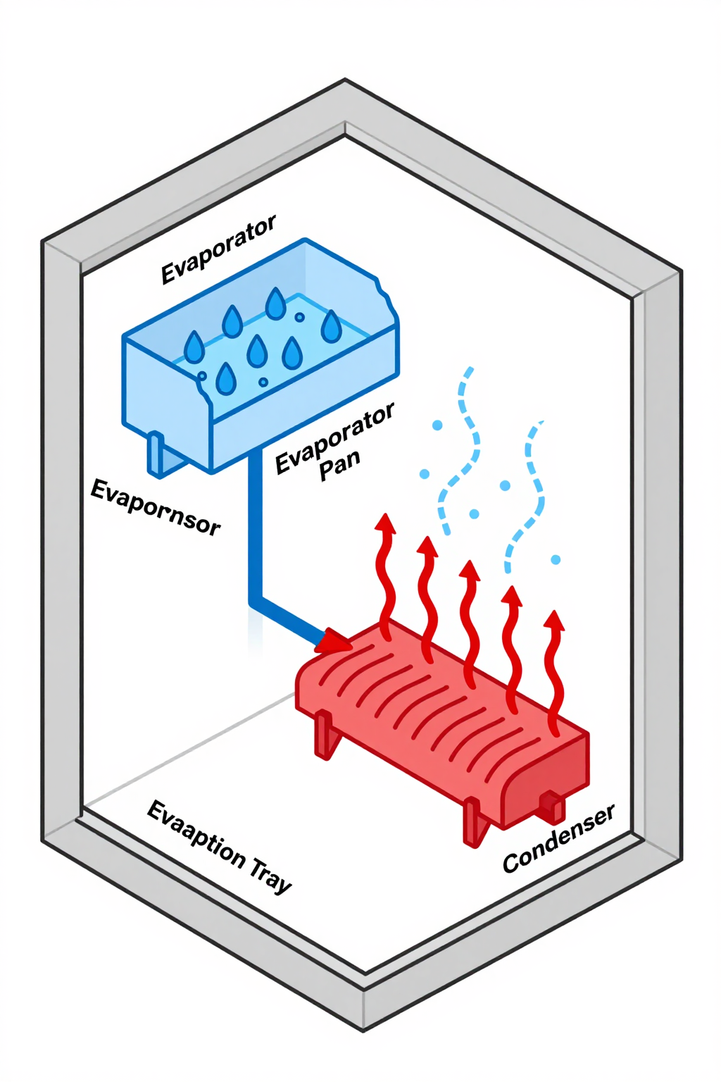
Re-evaporation is the most common condensate management approach for sealed enclosures that cannot drain externally. The principle is straightforward: collect condensate from the evaporator pan and route it to a location where it absorbs heat and returns to the vapor phase.
The most effective re-evaporation location is the condenser coil. The condenser operates at elevated temperature (rejecting heat from the refrigeration cycle to the outside), and directing condensate onto or near the condenser coil provides the thermal energy needed to evaporate the water. This approach has the added benefit of slightly improving condenser efficiency — the evaporating water cools the condenser coil surface, reducing the refrigerant condensing temperature.
Re-Evaporation Methods
- Condenser-mounted evaporation tray: A shallow tray positioned in the condenser airflow path. Condensate from the evaporator pan drains into this tray, and the warm condenser exhaust air evaporates it. This is passive and requires no additional energy or controls, but the tray must be sized for worst-case condensate generation rates to avoid overflow.
- Slinger ring on condenser fan: Some cooling module designs incorporate a slinger ring — a paddle or disc on the condenser fan shaft that picks up water from a collection basin and flings it onto the condenser coil as a mist. This accelerates evaporation and improves condenser performance simultaneously. The tradeoff is mechanical complexity and potential noise from water impingement.
- Heated evaporation basin: A small resistive heater in the condensate collection basin provides supplemental heat to accelerate evaporation during high-humidity conditions when condenser heat alone is insufficient. This adds power consumption but ensures complete evaporation regardless of ambient conditions.
The critical design constraint for re-evaporation is matching the evaporation rate to the condensation rate. If the evaporation system cannot keep up with condensate generation during worst-case conditions (high ambient humidity, frequent door openings, tropical deployment), the collection basin overflows and water enters the electronics zone — defeating the entire purpose of the system.
Dew Point Control: Preventing Condensation Where It Hurts
The alternative to managing condensate after it forms is preventing it from forming on critical surfaces in the first place. This requires controlling the dew point of the air inside the enclosure relative to the temperature of the coldest surfaces.
Condensation occurs on any surface whose temperature is below the dew point of the surrounding air. In a cooled enclosure, the coldest surface is the evaporator coil — and condensation there is expected and managed by the evaporator pan. The problem arises when other surfaces inside the enclosure also fall below the dew point — cable connectors near the evaporator, metal mounting brackets in the cold air stream, or the enclosure walls themselves during nighttime temperature drops.
Strategies for dew point control:
- Set the cooling module's target temperature above the dew point of the internal air at the expected humidity level. This prevents condensation on all surfaces except the evaporator coil. The tradeoff is a higher operating temperature inside the enclosure.
- Use desiccant packets or desiccant cartridges to reduce internal humidity below the level where condensation occurs at the operating temperature. Desiccants are effective in truly sealed enclosures with minimal air exchange, but they have finite capacity and must be replaced or regenerated periodically.
- Install anti-condensation heaters on critical components. Small heaters (typically 5 to 20 W) mounted on or near connectors, optical components, or high-voltage terminals keep the local surface temperature above the dew point. This is targeted protection rather than system-wide dew point control — effective for the most vulnerable components without heating the entire enclosure.
Condensate Volume Estimation
Sizing the condensate management system requires estimating how much water the evaporator will extract from the enclosure air. The calculation depends on the initial air volume, the humidity at the time of sealing (or door opening), the target internal temperature, and the evaporator coil temperature.
A simplified estimation approach:
- Determine the air volume inside the enclosure (total volume minus volume occupied by equipment)
- Look up the moisture content of air at the expected ambient conditions (temperature and relative humidity) using a psychrometric chart or table. For example, air at 35°C and 80 percent relative humidity contains approximately 28.7 grams of water per cubic meter
- Look up the moisture content at the evaporator coil surface temperature — this is the equilibrium moisture level the air will reach after extended cooling. For a coil temperature of 10°C, saturated air holds approximately 9.4 grams per cubic meter
- The difference — approximately 19.3 g/m³ in this example — multiplied by the air volume gives the initial condensate volume per cooling cycle after a door opening
For a sealed enclosure with 0.5 m³ of free air volume, this example yields roughly 9.6 grams (about 10 mL) of condensate per cooling cycle. This sounds small, but accumulated over multiple door openings, seal leakage events, and seasonal humidity variations, the total can reach hundreds of milliliters per year — enough to cause damage if unmanaged.
Frequently Asked Questions
Does a sealed enclosure eventually dry out if the seal is perfect?
In theory, yes — the initial moisture condenses on the evaporator, drains to the collection system, and the internal humidity drops to near zero. In practice, no enclosure seal is perfect over its operational lifetime. Thermal cycling creates pressure differentials that pump small amounts of ambient air through even well-designed seals. Component outgassing adds moisture internally. A condensate management system should be designed for continuous operation, not just initial dehumidification.
Can I just drill a drain hole in the bottom of the enclosure?
A drain hole compromises the IP rating unless it includes a sealed drain fitting with an appropriate trap or check valve. For IP55 and above, the drain must prevent water ingress during rain, pressure washing, or immersion testing. A simple hole — even pointed downward — will allow dust and moisture to enter the enclosure during wind-driven rain or during thermal cycling when negative internal pressure draws external air inward. Use a proprietary IP-rated drain fitting designed for the enclosure's protection class.
How do I know if condensate is causing problems in an existing installation?
Look for these indicators during inspection: visible water pooling in the bottom of the enclosure, white or green deposits on PCB surfaces or connector pins, musty odor when opening the enclosure, intermittent faults that correlate with cooling cycles or time of day, and corrosion on metal mounting hardware. An internal humidity sensor (if installed) showing sustained relative humidity above 70 percent is a strong indicator that the condensate management system is not keeping up with moisture generation.
Is condensate from the evaporator clean or contaminated?
Evaporator condensate is close to distilled water, but it picks up contaminants from the air (dust, flux residue, volatile organic compounds) and from the coil surface (metals, coatings, biological growth). Over time, the condensate becomes slightly acidic and can accelerate corrosion of untreated aluminum and copper. Do not assume condensate is benign — treat it as a potential contaminant in the drain path design.
Should I use a condensate pump instead of gravity drainage?
Condensate pumps are appropriate when gravity drainage is not feasible — for example, when the evaporator is at the bottom of the enclosure and the drain exit is at the top, or when the enclosure is below grade. However, pumps add complexity, power consumption, and a failure mode (pump failure leads to overflow). For most electronics enclosure applications, gravity drainage or re-evaporation is preferred over pumping.
How does ambient humidity affect cooling module sizing?
In high-humidity environments, a significant portion of the cooling module's capacity goes to latent cooling (removing moisture) rather than sensible cooling (reducing temperature). This means the effective temperature reduction for a given cooling capacity is less than what the datasheet implies. In tropical deployments, it is common to oversize the cooling module by 15 to 25 percent beyond the sensible heat load calculation to account for latent load during periods of high humidity ingress.
Integration Support
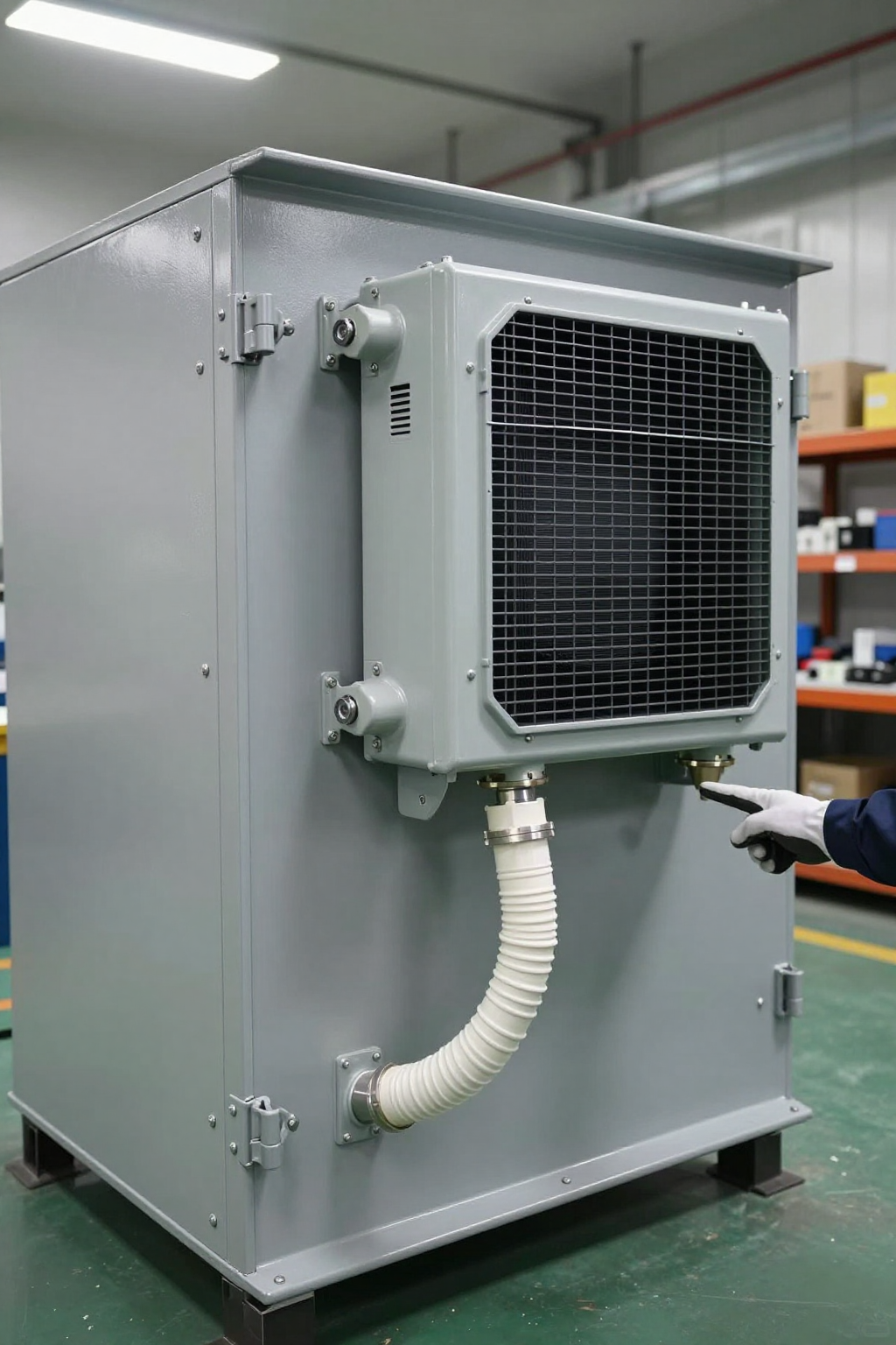
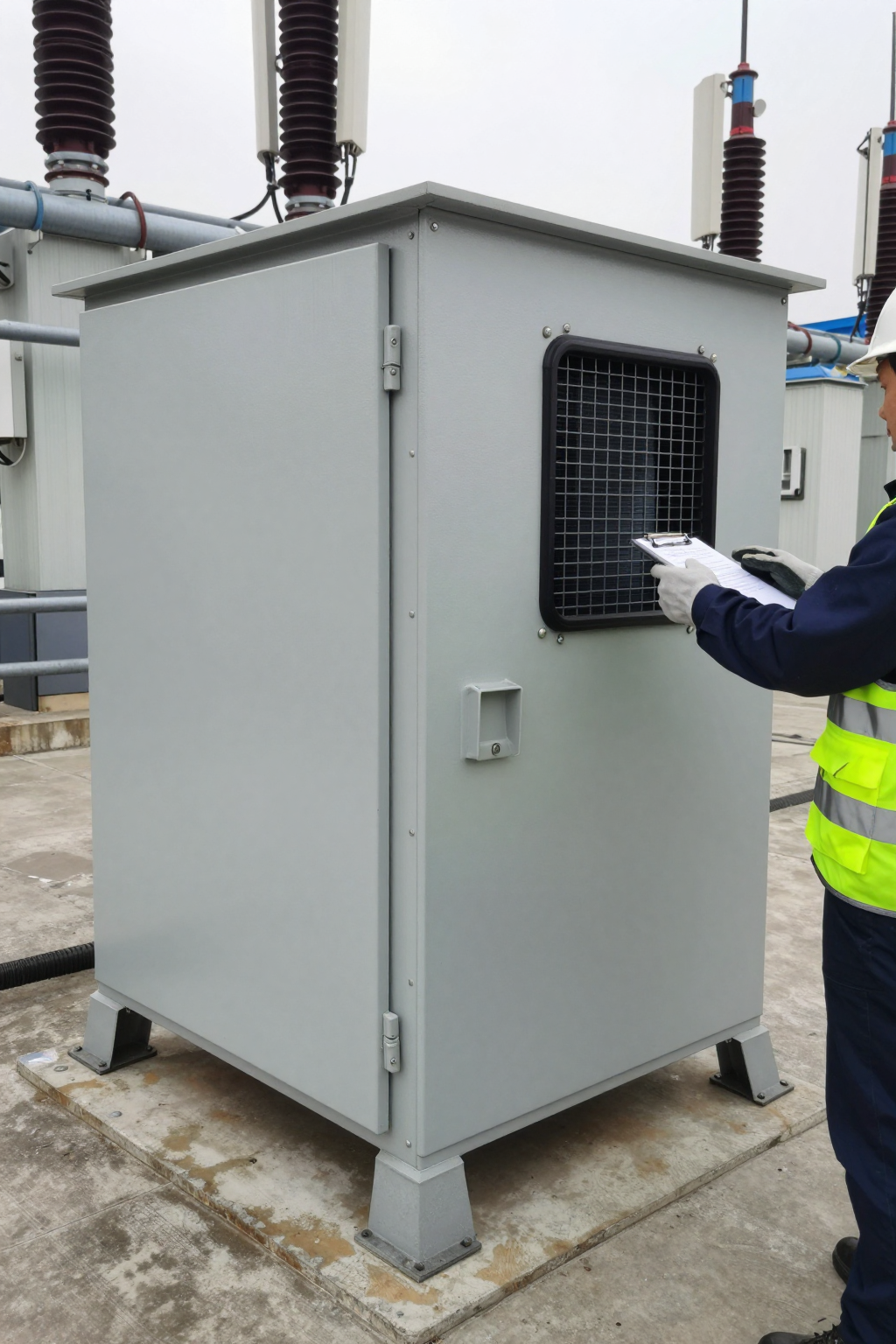
Condensate behavior depends on the interaction between cooling capacity, evaporator coil temperature, enclosure seal quality, and deployment environment — variables that differ substantially across applications. For enclosures where unmanaged moisture poses a reliability risk, the Rigid engineering team can assess the condensate load profile and recommend an appropriate management approach. The Rigid Micro DC Aircon series includes integrated condensate collection and can be configured with re-evaporation or external drain options to match the enclosure's environmental requirements and IP rating constraints.
Cooling systems remove heat. They also remove moisture. Designing for only the first and ignoring the second is how reliable electronics end up with preventable water damage — sometimes months after installation, always after the warranty review window.