
You have a product that needs active cooling. The thermal simulation says 300-800W of heat rejection. The power source is DC — a battery pack, a solar array, a vehicle electrical bus. Your procurement team is searching for a BLDC AC compressor that fits the mechanical envelope, hits the cooling target, and does not create integration headaches that push your timeline back six months.
This guide walks through the selection process from an OEM engineering perspective. Not marketing language. The actual decision points that determine whether a compressor works in your product or becomes an expensive lesson in thermal management.
What Makes a BLDC AC Compressor Different from Standard Units
The term "BLDC AC compressor" combines two concepts that initially seem contradictory. BLDC refers to the motor technology — brushless direct current. AC refers to the function — air conditioning (cooling via vapor compression refrigeration cycle). The compressor motor runs on DC power while producing the mechanical work to compress refrigerant in a cooling cycle.
For OEM selection, the BLDC motor architecture creates specific advantages over induction motors or brushed DC motors:
- Direct DC input. No inverter stage between your power bus and the compressor. The electronic commutation controller accepts DC voltage directly — 12V, 24V, or 48V depending on the model. This eliminates the AC/DC/AC conversion chain that wastes 10-15% of input energy.
- Speed modulation via electronic control. PWM signal or analog voltage input to the controller sets compressor speed. Your system microcontroller adjusts cooling capacity in real time based on temperature feedback, ambient conditions, or available power.
- Predictable electromagnetic signature. The switching frequency is fixed and known, making EMI filter design straightforward during qualification testing. Conventional brush motors generate broadband noise that is harder to suppress.
- No starting capacitor or relay. The electronic controller handles soft-start internally. Your power distribution design does not need to accommodate 3-5× inrush current spikes at startup.
BLDC AC Compressor Capacity Ranges and Model Selection
Matching compressor capacity to your thermal load is the first hard decision. Under-sizing means the system cannot maintain setpoint during peak conditions. Over-sizing means wasted cost, weight, and volume — plus short-cycling at low loads that reduces efficiency.
Available capacity ranges for miniature BLDC AC compressors in the RIGID QX series:
| Model | Voltage | Cooling Capacity | Refrigerant | Application Fit |
|---|---|---|---|---|
| QX1901VDL | 12V DC | 110-360W | R134a | Small enclosures, portable coolers, pet spaces |
| QX1902VDL | 24V DC | 125-400W | R134a | Equipment cabinets, medical devices, vehicle systems |
| QX1903VDL | 48V DC | 137-455W | R134a | Telecom cabinets, EV battery cooling, industrial |
| QX3202VDL | 24V DC | 550W | R134a | Larger cabinets, multi-zone systems |
| QX2802VDL | 24V DC | 550W (twin-cyl) | R134a | Low-vibration applications, precision equipment |
| QX2802VDL-T | 24V DC | 550W (twin-cyl) | R290 | Low-GWP requirement, regulatory compliance |
| QX3003VDL | 48V DC | 544W | R134a/R513A | High-voltage DC bus systems |
| QX8848VDL | 48V DC | 1,067W | R134a/R513A | High-capacity enclosures, server cooling |
| QX3803VDL | 48V DC | 646W | R134a | Mid-range 48V applications |
The capacity ranges shown (e.g., 110-360W for QX1901VDL) reflect variable speed operation. Minimum capacity occurs at lowest RPM; maximum at full speed. Your thermal design should target the 60-75% speed point for steady-state operation, leaving headroom for peak demand without running at maximum continuously.
Voltage Selection: Matching Your Power Architecture
The voltage decision is usually dictated by your existing power bus rather than being a free choice:
- 12V systems: Automotive accessories, small solar installations, single lithium cell configurations (3S-4S LiFePO4). Current draw is highest at this voltage — a 360W cooling load means 30A+ from the bus. Ensure your wiring gauge and connectors handle this.
- 24V systems: Professional equipment, larger vehicles, 7S-8S lithium packs. The most common choice for OEM integration because it balances current draw against voltage safety requirements. Most models available in 24V.
- 48V systems: EV-adjacent applications, telecom standard voltage, large battery installations. Lowest current for given power — a 1,067W compressor (QX8848VDL) draws only ~22A at 48V. Simplifies power distribution but requires attention to arc-flash potential at connectors.
Important: BLDC compressor controllers typically accept a voltage range, not a single value. A "24V" compressor may operate from 18-32V. This tolerance accommodates battery charge curves (fully charged LiFePO4 at 28.8V, discharged at 20V) without requiring voltage regulation. Confirm the specific operating range for your chosen model during evaluation.
Refrigerant Selection for OEM Applications
Refrigerant choice intersects with regulatory requirements, charge limits, safety engineering, and thermodynamic performance. For OEM products shipping globally, this decision has compliance implications beyond thermal performance:
R134a (GWP 1,430): The safe default for most applications. Non-flammable (A1 classification). Compatible with POE lubricants. Extensive performance data available. No charge-limit restrictions for A1 refrigerants in most jurisdictions. If your product ships to markets without specific low-GWP mandates, R134a minimizes qualification complexity.
R290 / Propane (GWP 3): Dramatically lower environmental impact. Higher COP than R134a in the 0-40°C operating range (typically 5-10% improvement). However: A3 classification (flammable). IEC 60335-2-89 and EN 378 impose charge limits based on room volume and ventilation. For sealed outdoor enclosures with charges under 150g, compliance is usually achievable. Models like QX2802VDL-T are engineered with appropriate charge limits.
R513A (GWP 631): A zeotropic blend that serves as a near-drop-in replacement for R134a with 56% lower GWP. Non-flammable (A1). Available in higher-capacity models (QX3003VDL, QX8848VDL). Useful when regulations push toward lower GWP but flammability is not acceptable for your application context.
Mechanical Integration: Mounting, Vibration, and Envelope
A compressor that fits the performance spec but not the physical envelope is useless. Key mechanical integration considerations:
Mounting orientation: Rotary BLDC compressors have preferred mounting orientations specified in their datasheets. Most operate correctly in any orientation except inverted (oil return depends on gravity in some designs). Confirm with the specific model documentation if your application requires unusual mounting angles — vehicle installations and marine applications frequently need non-vertical operation.
Vibration isolation: Even at partial speed, a running compressor generates vibration. Mount with rubber grommets or spring isolators to prevent transmission to the host structure. For precision equipment (lasers, measurement systems, medical imaging), specify the vibration spectrum from the compressor datasheet and design isolation accordingly.
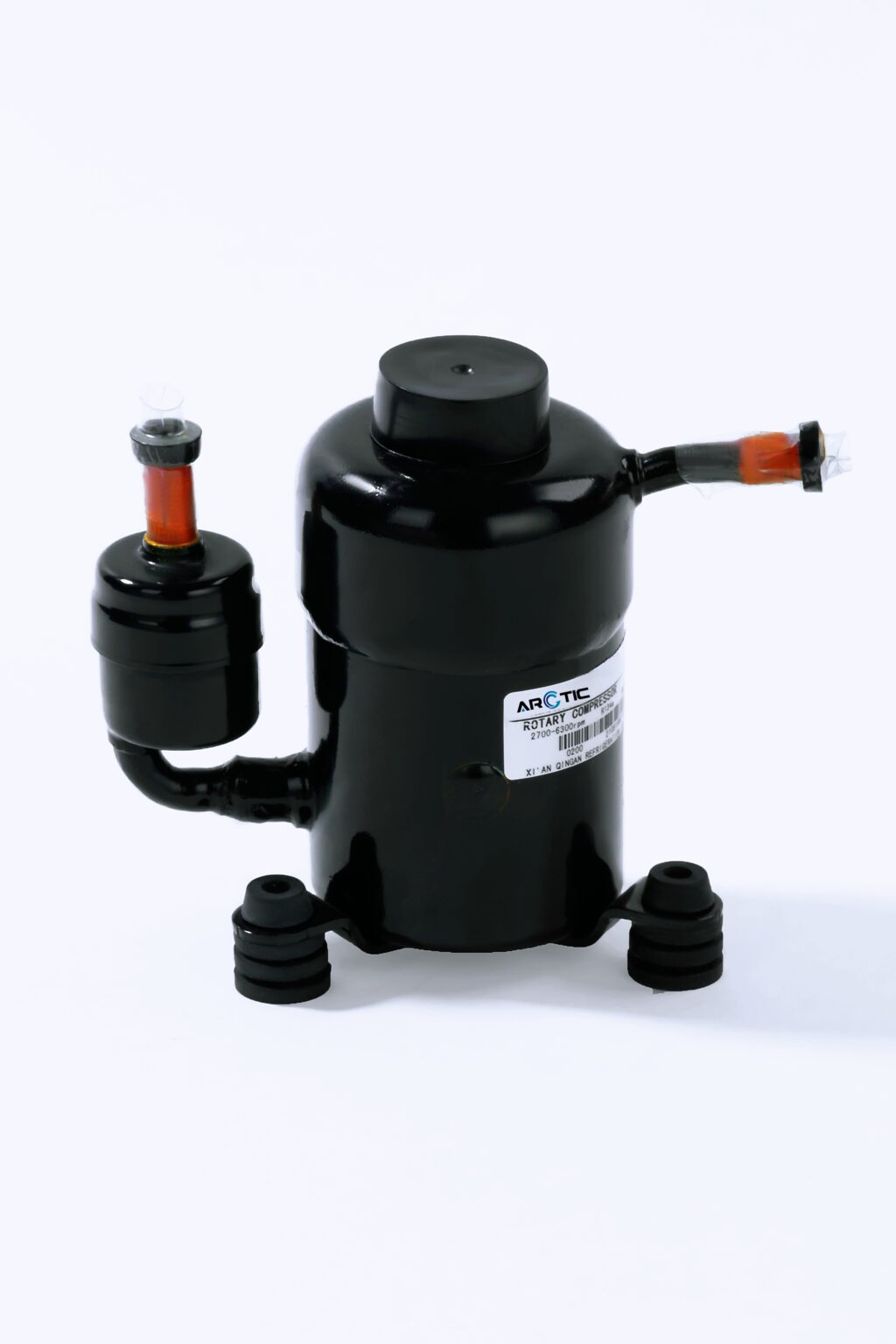
Envelope dimensions: The QX1901/1902/1903 series measures approximately 158mm × 89mm (body diameter × height). Twin-cylinder models (QX2802) are wider. The QX8848VDL is physically larger to accommodate 1kW+ capacity. Request 3D STEP files during evaluation to verify fitment in your CAD assembly before committing to a model.
Piping connections: Standard flare fittings on suction and discharge ports. Plan refrigerant line routing to minimize vibration-induced fatigue at connection points. Use flexible sections or loop stress relief near the compressor ports.
Controller Interface and System Integration
The BLDC motor controller is the interface between your system intelligence and the compressor hardware. Integration points to design around:
- Speed command input: Most controllers accept 0-5V analog, PWM (1-5 kHz typical), or UART/I2C serial commands. Map your system's temperature control loop output to the appropriate command range. A simple approach: PID controller output (0-100%) maps linearly to minimum-maximum compressor speed.
- Fault outputs: The controller reports over-current, over-temperature, low-voltage, and communication faults. Wire these to your system's safety monitoring. Define failure modes: does your product shut down gracefully or switch to a backup cooling mode?
- Enable/disable: A dedicated enable pin allows your system to start and stop the compressor independently of the speed command. Use this for system-level safety interlocks.
- Feedback signals: Some controllers output actual RPM, current draw, or compressor discharge temperature. These signals enable predictive maintenance algorithms and system health monitoring in field-deployed equipment.
Qualification Testing for Production
Before committing a BLDC AC compressor to production, your qualification program should verify:
- Thermal performance at boundary conditions: Test cooling capacity at maximum ambient temperature your product will encounter. Compressor capacity drops as condensing temperature rises — the datasheet nominal capacity assumes standard conditions (typically 35°C ambient, specific evaporator superheat). Your real-world conditions may differ.
- Voltage transient tolerance: Subject the compressor to expected power bus transients (load dumps, cranking events for vehicle applications, solar MPPT fluctuations). Verify the controller recovers gracefully without requiring manual reset.
- Vibration and shock: If your product is mobile, test per the relevant standard (IEC 60068-2-6 for vibration, IEC 60068-2-27 for shock). Pay attention to refrigerant line connections and electrical terminations.
- EMC compliance: Conducted and radiated emissions testing with the compressor running at various speeds. The BLDC switching frequency creates harmonic content — verify your filtering suppresses emissions below applicable limits (FCC Part 15, CISPR 14, or automotive CISPR 25).
- Life testing: Accelerated life testing under worst-case conditions establishes mean time between failures (MTBF). For products with reliability requirements (medical, telecom, military), this data supports your system-level reliability prediction.
For OEM engineering support, technical datasheets, and 3D models for the complete BLDC compressor range, contact the engineering team through Arctic-Tek DC Compressors.
Common OEM Selection Mistakes
Having supported hundreds of OEM integration projects, certain mistakes appear repeatedly:
- Sizing to average load instead of peak. Your compressor must handle the worst 5 minutes, not the average hour. If ambient temperature spikes to 50°C once per year, the compressor needs to maintain setpoint at 50°C.
- Ignoring condenser airflow. The most capable compressor underperforms if the condenser cannot reject heat. In sealed enclosures, plan for a condenser fan and adequate airflow path. Stagnant air around the condenser raises condensing pressure and reduces capacity by 15-30%.
- Specifying by cooling capacity alone. Two compressors with identical Watt ratings may differ in COP, noise, vibration signature, voltage range, refrigerant compatibility, and physical dimensions. The cheapest option is rarely the cheapest total system cost.
- Late-stage thermal design. Adding a compressor to a nearly-finished product design creates packaging compromises that degrade performance. Involve thermal management from concept stage to reserve volume, airflow paths, and power budget.
The right BLDC AC compressor simplifies your system design by eliminating the inverter stage, providing inherent variable speed, and offering direct DC compatibility. Get the selection right early and the integration follows naturally.
Supply Chain and Production Considerations
Selecting a compressor for prototype is one decision. Qualifying it for production at volume is another. Supply chain factors that affect OEM programs:
Lead time and MOQ: Standard models from established manufacturers typically have 4-8 week lead times for production quantities. Custom configurations (specific refrigerant charge, modified mounting, special voltage range) add 2-4 weeks for engineering and 4-6 weeks for production validation. Plan accordingly in your project timeline.
Incoming quality inspection: Define acceptance criteria for incoming compressors. Minimum checks should include: visual inspection for shipping damage, insulation resistance test (motor windings to case), refrigerant charge verification (by weight), and a brief run test verifying startup and steady-state current draw. Automated test fixtures at receiving reduce per-unit inspection cost at volume.
Traceability: For regulated products (medical, aerospace, automotive), ensure the compressor manufacturer provides lot traceability, material certificates, and test records. Establish this requirement during qualification, not after production starts.
Second source strategy: If your product volume justifies it, qualify two compressor sources for supply chain resilience. However, switching BLDC compressors is not trivial — controller tuning, refrigerant charge optimization, and thermal performance differ between manufacturers. Budget 3-6 months for second-source qualification.
Thermal System Architecture with BLDC Compressors
The compressor is one component in a vapor compression system. Its performance depends on the complete architecture:
Evaporator design: Size the evaporator for your target superheat (typically 5-8K for miniature systems). Undersized evaporators force the compressor to work harder, increasing discharge temperature and reducing COP. For air-cooled evaporators, ensure adequate airflow — a small fan drawing 2-5W dramatically improves heat transfer compared to natural convection.
Condenser design: The condenser must reject the cooling capacity plus the compressor work input. For a system with 500W cooling and COP 2.5, the condenser handles 500W + 200W = 700W of heat rejection. Undersizing here is the most common cause of poor field performance. In elevated ambient (45-50°C), condenser performance degrades precisely when you need it most.
Expansion device: Capillary tubes are simple and reliable for fixed operating conditions. For systems with widely varying ambient temperatures or cooling loads, a thermostatic expansion valve (TXV) or electronic expansion valve (EEV) optimizes superheat across the operating envelope. The BLDC variable speed already provides significant load-matching capability, so a capillary tube often suffices for moderate-range applications.
Piping layout: Refrigerant line sizing affects pressure drop and oil return. Follow manufacturer guidelines for maximum equivalent pipe length. Ensure oil return from the evaporator — avoid traps in suction lines that could accumulate liquid refrigerant or oil during low-speed operation.
Integration Checklist for Production Release
Before signing off on production, verify these integration items are complete:
- Thermal performance verified at worst-case ambient with production-intent hardware (not prototype with hand-brazed connections)
- EMC testing passed with compressor at minimum and maximum speed (different harmonic content at each speed)
- Vibration isolation validated — measure transmitted vibration at mounting points under all speed conditions
- Safety interlocks tested — high pressure cutout, low pressure cutout, over-temperature shutdown, loss-of-communication response
- Refrigerant leak rate confirmed below 3g/year for the assembled system (typical requirement for sealed systems)
- Controller firmware version locked — document which firmware version was qualified and establish change control
- Electrical connections rated for vibration environment — crimped terminals preferred over solder for mobile applications
- Service access planned — if the compressor is a field-replaceable unit, plan for refrigerant recovery, brazing access, and electrical disconnection in the product layout
The BLDC AC compressor represents a mature technology with thousands of successful OEM integrations in portable refrigeration, vehicle climate control, precision cooling, and industrial enclosures. Selecting the right model for your specific requirements — and integrating it correctly into your thermal system — determines whether the technology delivers its full potential in your product.
For technical specifications, application engineering support, and sample evaluation programs, visit Arctic-Tek DC Compressors.